Showing posts with label amplifier project. Show all posts

Tuesday, December 18, 2012

Part 4: The Finishing Touches - and Upgrades!

So far so good with the amp. It's been in service a week now and I have been able to really put it through its paces on a couple of bands. I finally decided to order an enclosure from Ten Tec. I chose one that is similar in size to the raw chassis that I was using as a makeshift enclosure. The new one is 9x9x4 (LxWxH) inches. That's 2 inches deeper an 2 inches taller, which by my measurements, should be a nice snug fit for all the filter boards and the keying board. Ten Tec enclosures are not the cheapest out there, but finding something this size for cheaper is really a crapshoot.

The new enclosure has black top and sides and the end panels are what Ten Tec calls an eggshell white. Since my heatsink is raw aluminum, I went ahead and tore down the amp, removed the PA board and painted it a nice Rustoleum satin black. Apparently it is important to use a primer when painting aluminum so I did that first.

It isn't a bad match and it will look nice on the desk for sure, though the Ten Tec case is more of a matte finish now that I have see it in person.

It is pretty sad to go maim a brand new case but I need to mount the heatsink in the top of the case. A big hole. For this task, I chose my handy dandy rotary hand tool, aka Dremel, with a cutting wheel. As always, measure 30 times, cut once! I went ahead and put the heatsink in the middle of the top cover and cut the whole just slightly bigger than the PA board itself.

The heatsink was already tapped for screws so once the hole was cut, I marked and drilled the mounting holes too.

I moved on to mounting the filters and keying board in the chassis next. Since each board is 2" wide, I had to stack one pair of them to fit the enclosure but I already had some threaded standoffs if you remember so that was easy. I lined all of them up in the case and marked and drilled those for 4-40 hardware.
Next I worked on the front and back panels.  I was really worried about screwing this up so there was a lot of measurement and test and fit and test and cut going on here!  I also added a 25A circuit breaker to the power input for a bit of protection.
Next the front panel went together.  No surprises here since its pretty basic and most of you have already seen my preliminary design for the front panel labeling.  It does sport a new dual color LED which is pretty swank:
During Recieve
And During Transmit
Luckily I got the band switch I ordered from China on Monday so I could button this whole thing up.  I went to town wiring up the filters to the switch, which was easier than I anticipated, but I did run out of coax so its only hooked up for 3 bands at the moment (40, 20, and 15).

Now we get to the upgrades! As you have seen, I built the keying circuit using a simple, cheap, 12v relay. It has been working fine but I have really found myself seriously missing my QSK, especially when I'm not using the amp and have the break in delay set high. So, since I've come this far already, I decided now is the time to add that solid state TR switch. There are a couple of ways to build one but I looked for inspiration in obvious places - Elecraft's K2 schematics. A fellow QRP op pointed me to the website of G3VMW who just happened to have built a fully home brewed transceiver that used the same AN762 amp and utilized a modified solid state TR switch from the K2. I copied his design as provided, plus one additional cap, and built it up in Eagle. Yet again, with the help of my Norwegian friend, Thomas, we laid out a PCB and everything. I have always wanted to learn how to do that and once I got a hang of the tool, it actually became really rewarding, almost like putting a puzzle together. At any rate, here is the board we ended up with.
3D render of the Gerber files from http://mayhewlabs.com/3dpcb
I went with Seeed Studio for the board fab, mostly based on price. The other houses I looked at were 2 or 3 times more pricey  Since Seeed is over in China, I'm not looking for boards for at least 3 weeks. Luckily I will be gone for nearly 2 weeks over the holidays so I couldn't play with any of that stuff if it were here anyway.

After all is said and done and the parts for the TR switch are added up, I think the total cost of the switch comes out to not much more than the relay based switch, and if it works, totally worth every penny.

So in preparation of the new switch, I just stuck the relay board to the case without any screws so I don't have any extra holes.

So the amp works! (still)  But now I'm on 3 bands!  Here's how she looks on the desk
Bland but it works!
And finally the gratuitous proof that the amplifier is amplifying - over 125w output with a couple watts of drive on 40m

Is it perfect? By no means (yet) but it sure works don't it?!  Now if only I could find a better knob for that band switch....

Monday, December 10, 2012

QROOO! Part 3: the PA

I received the amplifier kit from Communication Concepts today!  Here's what I found when I opened up the box:

On the left are the 5 band filters with the amp and parts to the right.  I was happy to see that the 3 transformers on the amp were pre-wound for me, which is nice since those are a bit special.  Luckily, there's still a few to wind for the filters!  It wouldn't be a real kit if I didn't have to wind any! 

I had scheduled some time with Rod, K0DAS, to help me drill and tap the heatsink for the board but he wasn't available right away so I put together the 20m filter while I waited.
20m Low Pass filter

It didn't take long for Rod to get back with me and I took the parts over to his QTH and we worked on drilling the holes for the amp.  It went fairly well and we got everything looking nice.  Only mistake we made was drilling the board mounting holes for 6-32 screws.  No big deal, we got the important ones right (the ones for the transistor tabs). We just drilled out the other holes to fit the bigger screws. I forgot to take a picture of the bare board mounted on the heatsink...oops!

Next, to start on the amp itself.  The "build notes" from CCI are little more than just that, notes.  These are not really "kits" in the traditional sense.  The build notes do outline generally how to assemble key parts of the board but do leave out some of the common details that might be included in a detailed, polished manual for example.  Keep that in mind if you are considering this journey in the future!  The initial assembly goes through the whole board minus the actual final transistors.  The last step before their installation is setting the bias current (and voltage).  It is very critical to set this correctly or else you will run a very serious risk of damaging the finals and they're $90 a pair so, play safe!

The assembly was pretty straightforward but the instructions did leave out a couple parts near the end - namely a couple of surface mount caps that go on the bottom of the board.  Once I figured out where they belonged, it was no problem.  
Board populated and ready for first smoke test
So with great trepidation, I applied power for the first time, monitoring the bias voltage across a 50 ohm resistor as requested in the build notes.  For some reason I was not getting anywhere close to the expected voltage.  Looking around I quickly found that the transistor and resistor in the bottom right of the board were getting very, very hot.  Something was clearly not right.  I inspected all the joints and part values and didn't find any issues.  Then just as I was getting frustrated, I spotted it, a tiny pinhead solder splash that crossed the bare board and must have been shorting the power rail to ground.  Once I flicked that off, the bias voltage came right into spec and the aforementioned parts were nice and cool too.

I applied thermal grease to the underside of the transistors and the thermal reference transistor (used as a PN junction) and bolted it all together.  Remember, a little bit of this stuff goes a long way and I bought a big jar (a couple ounces) which is enough for 50 amps.  Since my band switch is coming from China, it isn't here yet so I decided to just wire up the 20m filter directly to the amp for now.  Also, not having a chassis, I used the standoffs I had and threw it together like this:
Doesn't look pretty but sure works doesn't it?!
I timidly applied some RF while watching the output on an old MFJ tuner just to get a reference and sure enough, it was amplifying!  I also had the voltage meter on the KX3 up so I could see the supply during keydown.  I was surprised to see the voltage dipping quite a bit even though the power supply I'm borrowing is supposed to do 23 Amps continuous.  I'm thinking that spec is a bit generous.  Anyway, after some more testing and hooking it up to the scope, it looks like I'm putting out about 75+ watts with 5W of drive, maybe more.  I ordered a Powerwerx SS-30VD so hopefully it will be able to run a bit higher output with that.  Even if not, 75W is a big improvement over 5W, and the RBN spots prove it
40dB SNR?! Haven't seen that before!
I ran the amp like this a bit but it became pretty clear that this was a pretty poor setup for heat dissipation (the worst case one in fact) so the next day I decided to flip it over somehow.  I don't have a good case for it yet but luckily I did have the aluminum box from the antenna tuner I picked up at the junk in the trunk event in the Spring (see post about that here).  I have been working on getting that tuner cleaned up and serviceable but it'll have to wait for now.  Now, let me tell you, this chassis really makes the amp.  It looked pretty bad before, but now it looks like a real homebrew project!
Figuring out how to put all of it in the box
Wired up and ready for another test run
Power on - ready for QSOs!
Way cool right?!  Yeah, its not as streamlined or sexy as the KX3 but I'll be darned if it doesn't look like a real homebrew piece of artwork!  Ok, there's more work to be done, but this is going to work great for the short term, at least until the band switch arrives.  Until then, I have some more filter boards to wire up and QSOs to make!

PS: I intended to do a little video but my camera(s) were not cooperating last night so this will have to do!  Watch Twitter (@w0ea) and subscribe to my YouTube channel to keep an eye out for the video which I will post later! 

Friday, December 7, 2012

QROOO! Part 2: The Keying Circuit

As mentioned in Part 1, the keying circuit parts arrived first.
Keying circuit
I ordered some small prototyping boards for this circuit on eBay, assuming they'd be way cheaper than Radio Shack only to find that Radio Shack's boards are actually priced pretty well.  So rather than wait on those (could be days!) I went and picked up a couple before heading home for the day.

Here's all the key (hehe) components for this part of the build.  The relay I chose is Digikey part number Z147-ND, a DPDT, 8A, 12V relay.  This is the same relay that CCI uses in one of their other amplifiers that includes the keying circuit, so I knew it would work in this application.  The rest of the parts are generally generic parts and 1/4W resistors.  The 2n4401 and 1n4007 are staples in the junk box so I got several of both.  Resistors came from the junk box.  Most amplifiers use an RCA jack for the keyline input but LA3PNA suggested I just use a 3.5mm stereo phone jack instead since I have some on hand already and panel mount RCA jacks are at least a couple dollars.  Finally, I had to piece together a cable with 2.5mm plug on one end and 3.5mm on the other.  The 2.5mm plug was a calculator cloning cable in a previous life and the other end of it serves as the KX3 I/Q output cable.  So this should be enough to get this piece of the amp running.

Here's the board all wired up.  Proto boards are much nicer than trying to smash everything ugly style on a piece of copper!

I made a little video showing the relay switching when I hit the TX button on the KX3.  It works!

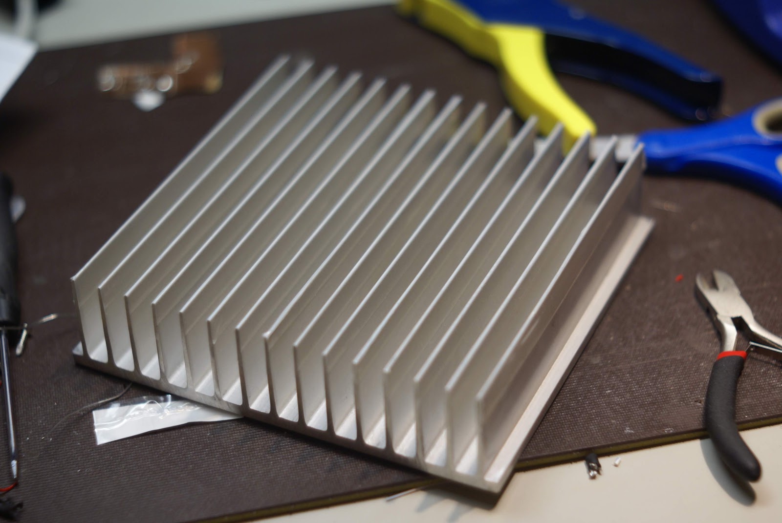
I also got lucky and another helpful ham you may remember, NM0S, Dave, found a heatsink for me to use.  He thinks its a bit big but it looks perfect to me.  I don't plan on cutting it down or anything.  I think its about 8 inches square and the fins are about 2 inches tall.  I could probably run RTTY at 100w for a while with this one!

Next step: build the amp board, which hopefully will be here on Saturday.  Check back for that!  Unfortunately I won't be able to complete the build on the amp board until I drill and tap the heatsink, so no on air testing this weekend.

Thursday, December 6, 2012

QROOOOOOOOOOOOOOO! (Part 1)


Yes, you read that right.  Me, a QRP evangelist if there ever was one, is getting an amp.  Well, not so much getting as building.

LA3PNA, Thomas, over in Norway tipped me off to a small mom & pop shop called Communication Concepts, Inc. near the venerable city of Dayton, OH.  They have a number of simple solid state amplifier kits for sale based off of old Motorola application notes.  After looking around, I settled on the AN762-140 model.  The AN762 is a 140 watt amplifier for 1.6-30 MHz.
The AN762 140 watt RF Amplifier (stock photo)
This is a pretty big step for me - I've built tons of kits now but this is a bit more than just a kit.  As you may notice, there's no enclosure, there's no keying circuit, there's no bandpass filters... this is really barebones.  Luckily CCI also has band filters for a mere $15 so I purchased filters for 5 HF bands 10m through 80m but the filters can probably be pressed into service on the nearby WARC bands in a pinch.  Filters will be switched by hand of course, a simple DP5T rotary switch direct from Hong Kong is on the way for that task.  

All that is left is T/R switching.  I would have loved to use PIN diodes, but I looked at some of the designs and they're all a bit more complex than I really need and since this is all homebrew, I can always upgrade in the future!  The design for the switch is nothing spectacular and is just a simple bipolar relay driver.  Initially I had thought the keyline on the KX3 produced a 3V output on keydown so I designed the switch using a single 2n4401 NPN only to find later that its just a logic zero (ground) output during keydown.  With LA3PNA's help (my analog skills are a bit rusty) we put together this circuit which "inverts" the NPN and switches the relay when the keyline is low since I had already ordered the NPNs.
Keying circuit
The value of R1 is kind of arbitrary but you want to limit the current dumping through the KX3's keyline so chose something big-ish.  I've successfully simulated the design with resistors as big as 1M Ohm so take that for what it is.  

So save for a bit of coax, a chassis, and some connectors, that's pretty much the hole concept of the amp.  It does require a heatsink of course, and I'm still trying to dig one up on the cheap.  I'm sure it will come together when I finally have all the electrical parts in hand and can figure out how I want to lay everything out inside the case I still don't have either!  

Since I ordered from multiple vendors, I will be receiving parts in stages, with the keying circuit parts arriving first so my next post will be about constructing and testing that.  I'll be sure to include pictures.  Keep an eye out for part 2!